|
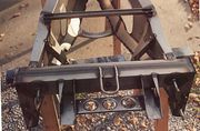
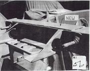
A 12 gauge (2.66mm) panel welded to the underside of the front
cross-member, where the jack is usually and erroneously - placed when lifting
the front of the car. A tow loop may be welded to this plate. Many Elans have had their bump steer
readjusted by moronic towing attempts from the big holes in the rack
|
|
|
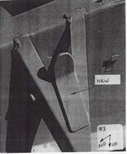
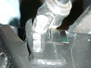
A new, thicker 14 (1.9mm) gauge, inboard sway bar support tab added
on each side (left picture not drilled through yet).
|
|
|
|
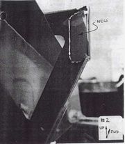
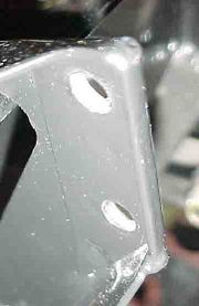
A 16 gauge (1.9mm) reinforcing
pad spot welded to the aft side each engine mount, to
alleviate the cracking that frequently occurs here (left picture not drilled
through yet). Later models may have come from the factory with these.
|
|
|
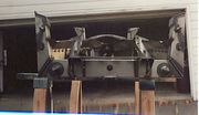
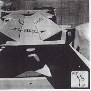
14 gauge (1.9mm) reinforcing strips
welded in along the whole length of the underside of the central frame, on
both sides. The openings should be closed off in the
front to prevent scooping up dirt and road debris. Note the differential
torque rod mounting blocks, described in the next photo. This modification
may require re-routing of the rigid brake line through the tunnel due to the
position of the exhaust pipe. It is probably a good idea to drill some holes
and spray a rust retardant in the closed areas.
|
|
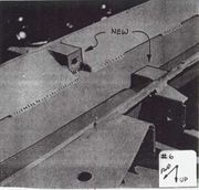
The holes (early models) or stock
welded-on differential torque rod studs (later models) replaced with drilled
steel square stock through which longer standard bolts are installed to
secure the torque rods
|
|
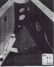
14 gauge (1.9mm) reinforcement pads
welded, on each side, on the bottom side of the top flange of the arms
forming the engine bay, just forward of the curved cross-member. This area
often develops distortion and cracks
|
|
|
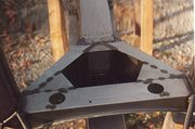
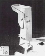
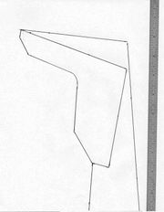
Reinforcement of the rear strut towers
with a welded-on 14 gauge (1.9mm) plate on the aft side. Template for
strengthening the rearmost two towers by welding in 14 gauge triangular
gussets.
|
|
|
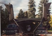
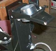
These "wings" are three point
seat belt mounts, welded directly to the chassis. This was less expensive
than having original style brackets fabricated
|
|
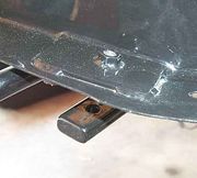
Replacement of the cross-member under the
engine with one that is removable. The cross-member is a hollow rectangular
tube with the ends filled with solid stock and drilled. Note the 14 gauge (1.9mm)
reinforcing plates on the top side of the cross member anchoring points
|


